What is Laser Welding?
Laser welding is a process used to join metals or polymers by heating two or more parts at their contact surfaces with a laser until a localized melt region forms, spanning the parts and fusing them together as the melted material cools.
First developed in the 1970s, laser welding has exploded in popularity in recent years. This is due to its speed, repeatability, fine weld geometry, and reduced heat-affected zone (HAZ) compared to other techniques. The associated services and equipment costs continue to decline, resulting in increased adoption across many applications. Examples include hermetic packaging of electrical components, aerospace, automotive, biomedical devices, and even jewelry manufacturing.
Precision and Control: Laser Weld Parameters
Laser welding provides manufacturers with an unprecedented level of control. An operator can manipulate laser power, pulse duration, frequency, feed rate, and beam diameter to influence various weld characteristics, including weld and HAZ geometries. Users can also adjust parameters to mitigate common issues like cracking, voids, or incomplete fusion of the target components.
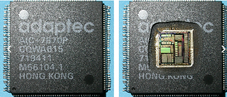
Hermeticity & Medical Device Manufacturing
Implantable medical devices are some of the most demanding laser welding applications, requiring a lasting hermetic seal under extreme conditions. In addition, they are held to some of the highest standards of quality, safety, and longevity while being subject to strict oversight and step-by-step approval from governing bodies.
Nowhere is this more evident than in the construction of life-sustaining devices like pacemakers, whose failures can result in severe injury or even death. The steady introduction of laser welding has enabled medical device manufacturers to simultaneously increase throughput, improve reliability, minimize fallout, expedite production scaling, and potentially save lives.
Welding vs. Soldering for Challenging Environments
Minimizing imperfections and variations between welds is critical to improving the longevity of your product lines. This is particularly true of products utilized in harsh environments. Even under relatively moderate and livable conditions, consumer product components like electric vehicle battery packs and solar panel collectors experience regular swings in temperature, humidity, and other environmental conditions. Laser welding, in lieu of standard soldering, produces bonds with superior mechanical and electrical properties. Furthermore, welding increases the already impressive lifespan of these relatively recent additions to the consumer medical products market.
Laser Weld Analysis: Iron-Aluminum Bonding
Welding dissimilar metals is both extremely useful and challenging. However, achieving success provides much-needed flexibility for your product design. Our lab received a sample consisting of aluminum and iron foils, which were joined by laser welding. We encapsulated the sample in Buehler EpoxiCure 2 and mechanically cross-sectioned it through the welded region at a pre-determined orientation. We documented the weld region using a Leica DM2700M compound microscope equipped with a Leica K5C digital camera.
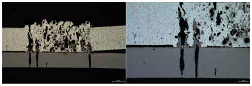
Several characteristics stand out in the images above, but none more so than the large voids in the target foils. The laser clearly targeted the aluminum foil on top, and we can see three regions (two on the far left and one on the far right) where the laser penetrated the upper foil and formed large voids in the underlying iron foil. Intermixing of the metals appears limited, and the 3 previously mentioned regions show near or complete over-penetration, with the resulting voids extending to the bottom surface of the iron foil.
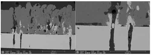
SEM Laser Weld Analysis
We coated the cross-sectioned sample with several nanometers of gold/palladium and examined it using a ThermoFisher Scientific Apreo S field emission scanning electron microscope (SEM). We captured images using a backscatter electron (BSE/CBS) detector to enhance the contrast between the aluminum and iron.
The BSE SEM images better highlight the presence of iron in the aluminum foil layer. Although the pockets of iron within the aluminum foil do not align with the three large regions at which the iron foil melted, it is reasonable to conclude that they originated from sites of melted iron that have already been polished through or which may be accessible through further polishing.
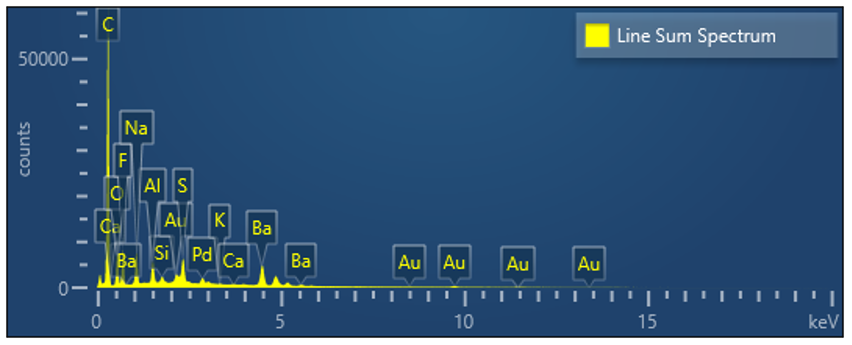
We collected elemental maps and an overall spectrum at the weld site using an Oxford Instruments Ultim Max 100 energy dispersive X-ray spectroscopy (EDS) detector.
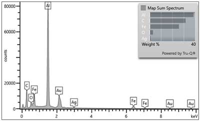
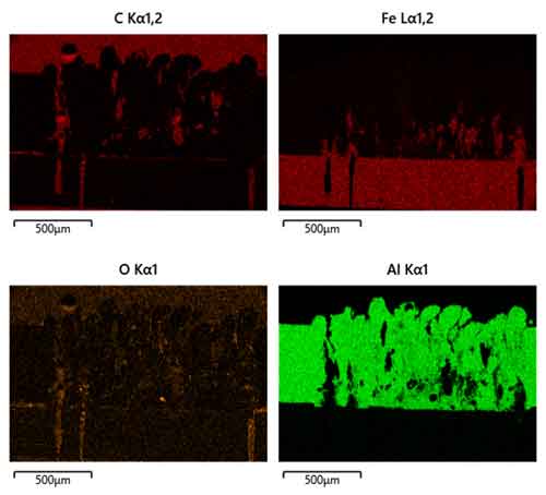
In addition to highlighting material intermixing, EDS is helpful in identifying regions of local oxidation, a phenomenon to which both aluminum and iron are prone. While convenient, laser welding in the atmospheric gases greatly increases your chances of generating oxides. These oxides can prevent intermixing, weaken welds, and reduce electrical and thermal conductivity.
Have questions or need help with your application?
Learn about our laser welding analysis services, or contact us.